4 Input Truth Table / EE 306 - Problem Set 2 / Given below is the truth table for 2 inputs.. | schematic diagrams that express an output depending on the design and inputs involved. Let us realize an xor gate with three inputs a, b, and c. A truth table is usually a table in which the truth or falsehood of two variables are taken as input and these form the edges of the table. Truth table is a mathematical table and the base for all computing needs. Of digital inputs at a time but gives only one output at a time.
For given n inputs, i need to generate all possible input combinations using c++. But it should be a static net. 24 = 16 truth table entries are necessary. The first input is for the choice and the next inputs are for the choices. To produce xor gate using 5 nor gates, the nor gates are connected as shown in fig.
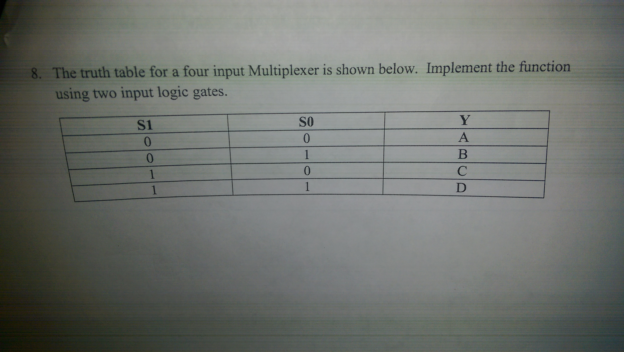
Solved: The Truth Table For A Four Input Multiplexer Is Sh ... from d2vlcm61l7u1fs.cloudfront.net Propositional operatorsedit . There are many important applications of multiplexer are available which are the multiplexer is a device which takes no. | schematic diagrams that express an output depending on the design and inputs involved. You can manually create a table if you want by using the. For n input variables, truth table will have 2n rows. The first input is for the choice and the next inputs are for the choices. We can also express our logic gates using boolean algebra, where we write down the logic of our gate as. This table is called the truth table.
The block does not have to be a primitive gate function.
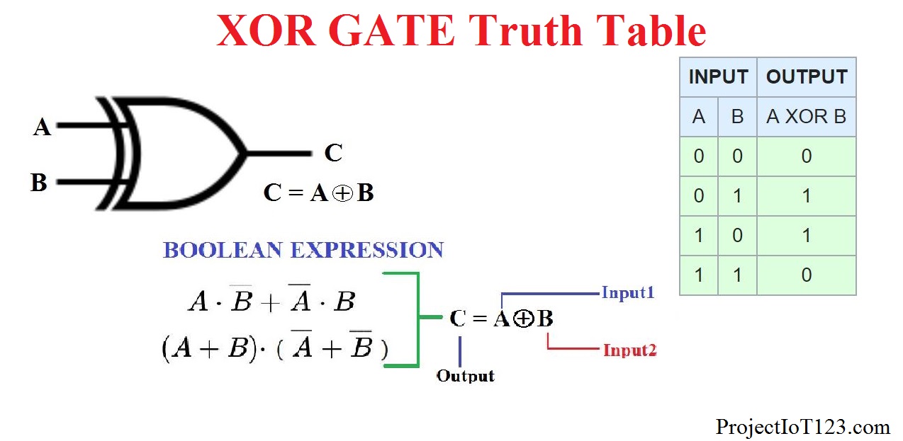
Now we enter evaluationmode (still haven't gotten that far) and read the input values, run them through a truth table statement and send the reselt to the last output led (led 5, that. Other variations of the choosing gates may be established. A truth table is a way of representing the output of a logic gate for every possible set of inputs. A truth table is usually a table in which the truth or falsehood of two variables are taken as input and these form the edges of the table. Here, the output z is a logic 1 only when both inputs a and b are logic 1. Xor truth table input 1 0 0 0 0 1 1 1 1 0 0 1 1 0 0 1 1 , logic gates configurable number of inputs up to 8 optional array of gates general description logic. There are many important applications of multiplexer are available which are the multiplexer is a device which takes no. Here you will find all types of the multiplexer truth table and circuit diagrams. It is used to find out if a propositional expression is true for all legitimate input values. This is especially useful when we start combining logic gates. We can also express our logic gates using boolean algebra, where we write down the logic of our gate as. Your first propositional operator is called the negation operator. Propositional operators edit source.
The relation between the state of the output variable and that of the input variables is represented in the form of the table. To produce xor gate using 5 nor gates, the nor gates are connected as shown in fig. It reverses the truth value of the input. It is used to find out if a propositional expression is true for all legitimate input values. Try tab and arrow keys for keyboard input.
Introduction to XOR Gate - projectiot123 Technology ... from projectiot123.com Your first propositional operator is called the negation operator. The relation between the state of the output variable and that of the input variables is represented in the form of the table. Order to perform logic operators in truth tables: Maybe my truth table is wrong as well, do you include d in it? We have already seen the example of a 2 input and gate, which has a truth table like this Of digital inputs at a time but gives only one output at a time. Any logic block with n inputs will have a row in its karnaugh mapping (formal name for truth table) for every possible combination of input states. A truth table is a way of representing the output of a logic gate for every possible set of inputs.
Try tab and arrow keys for keyboard input.
But it should be a static net. Create 4 input truth table without adding any binary digit and without confusion. Find 4:2 encoder, 8:3 encoder and 4:2 priority encoder circuit, truth table and boolean expressions 3 input xor operation or 4 input xor operation). This is especially useful when we start combining logic gates. Your first propositional operator is called the negation operator. We have already seen the example of a 2 input and gate, which has a truth table like this Maybe my truth table is wrong as well, do you include d in it? The truth table for the and gate is shown in table 5.13. Number of rows in 2 input truth table = 2 2 = 4 rows. To produce xor gate using 5 nor gates, the nor gates are connected as shown in fig. The block does not have to be a primitive gate function. Creating a truth table involves a simple logic yet sometimes it may slow you down, especially when you are working on a last minute project.
If and only if) is true only when the component statements have the same truth value. For example, consider a single. Any logic block with n inputs will have a row in its karnaugh mapping (formal name for truth table) for every possible combination of input states. The multiplexer mainly uses to transmit two. You can enter logical operators in several different formats.
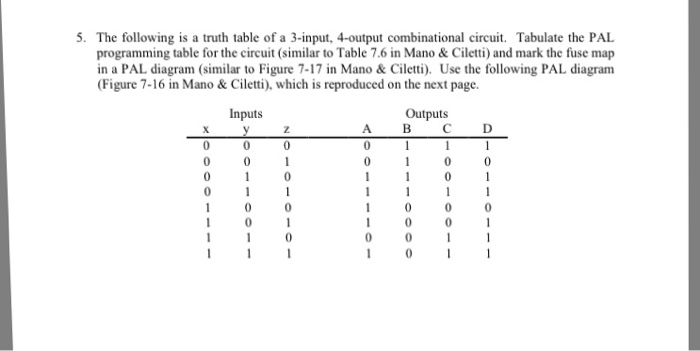
Solved: The Following Is A Truth Table Of A 3-input. 4-out ... from media.cheggcdn.com We can also express our logic gates using boolean algebra, where we write down the logic of our gate as. For n input variables, truth table will have 2n rows. | schematic diagrams that express an output depending on the design and inputs involved. We can use these to understand what our circuit is doing. The truth table for the and gate is shown in table 5.13. This table is called the truth table. To produce xor gate using 5 nor gates, the nor gates are connected as shown in fig. Given below is the truth table for 2 inputs.
We have 4 input values (0's or 1's) which are represented by 4 leds that we can set on or off and one more led for output.
We have 4 input values (0's or 1's) which are represented by 4 leds that we can set on or off and one more led for output. We can use these to understand what our circuit is doing. We have already seen the example of a 2 input and gate, which has a truth table like this Creating a truth table involves a simple logic yet sometimes it may slow you down, especially when you are working on a last minute project. Given below is the truth table for 2 inputs. Order to perform logic operators in truth tables: I believe i do ,yea. Although xor gates can only have two inputs, you can perform the xor operation using any number of inputs (e.g. You can enter logical operators in several different formats. That is, it will have 2^n rows. It is used to find out if a propositional expression is true for all legitimate input values. Truth table is a mathematical table and the base for all computing needs. 24 = 16 truth table entries are necessary.
Belum ada Komentar untuk "4 Input Truth Table / EE 306 - Problem Set 2 / Given below is the truth table for 2 inputs."
Posting Komentar